CROSSFIRE
CROSSFIRE PRO Troubleshooting
Assembly
1: Safety
Please refer to the Safety section of your machine's Assembly Guide.
CrossFire: https://www.langmuirsystems.com/crossfire/assembly#safety-section
CrossFire PRO: https://www.langmuirsystems.com/pro/assembly#safety-section
2: Assembly Guide
The complete CrossFire and CrossFire PRO Assembly Guides can be found on our website:
CrossFire: : https://www.langmuirsystems.com/crossfire/assembly
CrossFire PRO: https://www.langmuirsystems.com/pro/assembly
3. Missing or Incorrect Components
If you seem to be missing any components, reach out to us and we can get them sent your way ASAP!
Email: support@langmuirsystems.com
Phone: (833) 526-4797
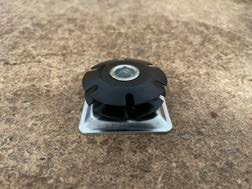
4: Leveling Foot/Caster Insert does not look like the one shown in the Assembly Guide
The shape of the leveling feet inserts is difcult to render in the 3D modeling program we use to create the images for our assembly instructions, so the actual leveling feet inserts look a bit different from the rendered leveling feet inserts in the CrossFire PRO assembly instructions. The correct Leg Tube Insert should look like the component shown here:
5: Motor Mount/Bearing Mount holes misaligned
A. Before lifting with an Engine Hoist/Shop Crane, the Crossfire must be maneuvered so that the Hoist can be properly positioned.
B. It's also possible that the gantry tube was installed upside down. Try rotating the gantry tube 180°
6: Lead Nut mounting holes misaligned
The next step is to utilize your shop crane to access the final lift point.
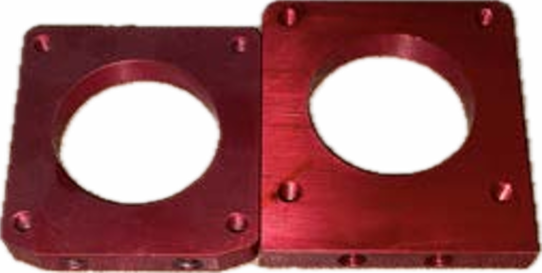
Incorrect Lead Nut
The Lead Nuts come in two sizes: 3/8” (rounded square shape) and 1/2” (diamondshape). The CrossFire uses two 3/8” Lead Nuts, while the PRO uses two 3/8” Lead Nuts and one 1/2” Lead Nut.
Inspect the Lead Nuts that came with your machine and reach out to Langmuir Systems Support if you seem to have received the incorrect set.
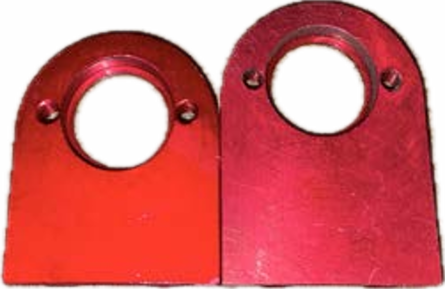
Incorrect Lead Nut Mounting Tab
If the Lead Nuts are correct, it's possible that the gantry assembly of your machine was assembled with the incorrect Lead Nut Mounting Tab(s).
The CrossFire should have two Lead Nut Mounting Tabs, each with four mounting holes to align with the rounded square shaped Lead Nuts. If one or both of the Mounting Tabs appear to be incorrect, reach out to Langmuir Systems Support for a 3/8” Lead Nut Mounting Tab.

Conversely, the CrossFire PRO only has one Lead Nut Mounting Tab, as the Y-axis Lead Nuts are mounted directly to the Carriage Weldment. The PRO's X-axis Lead Nut Mounting Tab should have two holes, to align with the diamond shaped Lead Nut. If your Lead Nut Mounting Tab appears to be incorrect, reach out to Langmuir Systems Support for a 1/2” Lead Nut Mounting Tab.
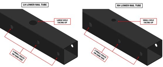
7: Received Identical Lower Rail Tubes (PRO Only)
If you received identical Lower Rail Tubes, you'll need to reach out to Langmuir Systems Support for the correct component. The Lower Rail Tubes are not interchangeable.
The replacement process could be expedited if you inform our team as to whether you need a Right-hand (RH) Lower Rail Tube or a Left-hand (LH) Lower Rail Tube. Using the photo below, identify the Lower Rail Tube you received a duplicate of, and include that information when you reach out to our Support Team.
8: Break-in Program throws Limit Switch Error
The break-in program was designed before the Limit Switch Kit came out. By design, the break-in program is supposed to run the entire area of the travel machine; thus, it may get very close to or cross a soft limit, prompting a soft limit error.
Take note of your soft limit values, then disable Limit Switches via the Machine Settings window and run the run-in program. Re-enable Limit Switches once the break-in program is complete.
Leads (Motors, Lead Screws, Lead Nuts)
1: A motor appears to be stalling
Coupler Slipping
The motor coupler may be loose, not properly gripping the lead screw or the motor shaft. An easy way to check for motor coupler slippage is to take a sharpie marker and make three dots that are lined up to one another: one dot on the motor coupler, another dot directly next to it on the motor shaft, and another dot directly next to it on the lead screw. If the dots do not stay aligned to one another as the machine jogs, the cause of the issue is denitely related to motor coupler tightness. Try tightening the set screws in the motor coupler until they cannot be tightened any more.
Mechanical Binding
Mechanical binding occurs when something prevents the smooth movement of the lead nut along the lead screw. This could happen for a few reasons:
A. The lead screw may be dry. Lubricate with machine oil and jog the machine to ensure that lubricant also gets into the threading of the lead nuts. We do not recommend lubricating the lead screws with white lithium grease, WD-40, or dry lube.
B. An incorrect bearing mount might have been used. The X-axis motor and bearing mounts are shorter than those used by the Y-axis. Measure the bearing mounts on your machine and conrm that the X-axis bearing mount is not the same length as the Y-axis bearing mounts, and that the length of the Y-axis bearing mounts is identical to one another.
C. The motor or bearing mounts may be out of square, causing a slight ex in the lead screw. Visually inspect that the mounts are mounted onto the gantry rails as square as possible, using a protractor if necessary.
D. The lead screw may be bent. Uninstall the lead screw and check it for a bend by rolling the lead screws along a clean, at surface. If you identify a bend, try to straighten it by using light hand force.
E. The lead nut might be improperly installed on the lead screw. Uninstall the lead screw from the machine, then uninstall the lead nut from the lead screw. Compress the spring on the lead nut to fully open it, and keep the spring compressed while you install it onto the lead screw.
F. The lead nut mount tab may be out of square. This is an extremely rare issue, and you can identify it by loosening the four bolts and nuts that mount the lead nut until the lead nut can be wiggled around by hand. Once the lead nut is mounted slightly loose, attempt to jog the machine
G. One of the motor plugs might have experienced arc damage, or has a loose connection to the motor port. This is most commonly the issue if one of the motors seems to intermittently be jogging the incorrect direction. With the CNC electronics enclosure powered off, disconnect the motors from the motor ports and inspect them for signs of arc damage. Arc damage would present as burning, melting, charring, darkened areas, etc. If no damage is present, reconnect the motor plugs to the motor ports and secure the connection using the D-sub screws. Ensure there is no play at the motor connections when the D-sub screws are tight by mimicking the motion of unplugging the motors while the D-sub screws are secure.
2: A motor is not responding or is moving erratically
A. Inspect the pin of the affected motor's plug for signs of damage from arcing, which would appear as burn marks, melting, scorching, etc. If arc damage is present, reach out to Langmuir Systems support for a replacement motor and Dsub connector
B. When the Electronics Enclosure is powered on, do all the Step Drivers have illuminated status LEDs? The Step Drivers are the series of black and green components in the enclosure. If not, reach out to Langmuir Systems support for a replacement Step Driver.
3: A motor jogs in the incorrect direction
Switching the polarity of the associated step driver should clear this up. Inside of the electronics enclosure, identify the step driver associated with the motor moving the incorrect direction by backtracking the wiring from the motor to the Electronics Enclosure. The step drivers are the black and green components on the right-hand side of the electronics enclosure. You can also backtrace the motor cable of the motor moving the incorrect direction to its motor port, then backtrace the motor port to the step driver it is connected to inside of the enclosure.
Note that the wires going to the step driver are attached to green quick-connect clips, which are labeled on top. Disconnecting and switching the green and red wires corresponding to the quick connector locations labeled A- and A+ will reverse the travel direction of the motor.
Software
1: Common FireControl Error Messages
Child Process Error
A "child process error" occurs when a subprocess created by a program (the "parent process") runs into a problem that prevents it from completing its task. In the case of FireControl, the digital read-out and toolpath visualizer are examples of child processes. Generally, such errors have various causes, such as insufcient system resources, hardware failures, or CPU driver issues.
We're aware of a rare Windows issue that can cause this error when trying to run FireControl; it appears to be related to how the OS handles power efciency, as it seems to have affected specically power-efcient CPU models. Child process errors are Windows OS-level CPU errors, not a FireControl error; in other words, this issue is stems the computer, not a problem with the FireControl software.
The best first step get a completely fresh FireControl installation, following the step outlined in the FireControl Reinstallation section. If the issue persists, try again, this time installing the "compatibility" version of FireControl.
It's possible for this issue to persist after a fresh FireControl installation. Users have reported resolving it by updating their CPU drivers or computer's BIOS. Updating drivers and BIOS can be drastic steps, so it's best to proceed with caution.
That said, the step outlined above may not resolve the issue, and a different computer may have to be utilized to run your machine. We've noticed that this issue affects laptops equipped with power-efcient processors in particular. Such processors are often differentiated by “U” being the final character of their model number.
Torch Moving Before Cutting Voltage Sensed
Refer to the AUTOMATIC TORCH HEIGHT CONTROL (THC) - THC Voltage Error section of this guide.
Plasma Cutter Misfire Detected
Refer to the PLASMA CUTTER - Misfire section of this guide.
IHS Fail
Refer to the Z-AXIS - IHS Fail section of this guide.
Program Check Encountered an Error
This error message indicates a general error with the G-code le you have uploaded to FireControl. Common causes include using the incorrect PostProcessor or uploading a G-code le that surpasses your specied Soft Limits.
Homing Fail
Homing failures are issue that prevent the homing sequence to complete successfully. For instance, if the amperage of the Step Drivers was not properly configured in our facility, the motor would not back off the Limit Switch enough to deactivate it; in this instance, check the dip switches of
2: FireControl Reinstallation
When FireControl is installed, a separate directory is created to store data like preferences, soft limit values, program history, etc. When FireControl is uninstalled, this directory remains on your computer so that your settings remain consistent between installation. As such, if any issues or bugs stem from that directory, a simple uninstall would not resolve the issue; it must be removed before FireControl is reinstalled. Keep in mind that this folder is easily-accessible on Windows, but can be difcult to locate to on Mac, often requiring use of the terminal.
1. Uninstall FireControl from your computer via the Control Panel.
2. Delete the .FireControl folder.
On Windows, it is located at C:\Users\[YOUR USERNAME]\.FireControl
On Mac, it is located at ~/Users/[YOUR USERNAME]/.FireControl
3. Restart your computer.
4. Reinstall FireControl.
3: Toolpath Visualizer not appearing
The Toolpath Visualizer can be enabled via the “View” tab in the top-left corner of the window.
If the issue persists, I recommend first trying a fresh FireControl installation. This process is outlined in the FireControl Reinstallation section.
4: FireControl Not Connecting to CrossFire
If your CNC electronics enclosure is plugged into your computer but fails to autoconnect, you may need to manually connect the device. Next to 'Machine', click the 'Connect' button to drop down a list of available machine connections and select CrossFire from this menu. If connected properly, this LED should turn green like the previous auto-connect image representing a positive connection.

If the issue persists, follow these steps:
A. Ensure that the CrossFire machine you are attempting to connect to is a Gen 2 FireControl-compatible CrossFire. FireControl-compatible machines have an electronics enclosure with Z-Axis motor port. Legacy CrossFire machines require the use of Mach3 as control software.
B. Try manually installing the FireControl CrossFire Gen2 Driver from our Downloads Page. Manual driver installation is a required step for Windows 7 and Windows 8 devices.
C. Plug in your CrossFire machine via USB directly, without any USB extensions or Hubs.
D. If the 'CrossFire' text is slightly greyed out without listing the Firmware version, wait 10 seconds with FireControl open for the Connection Help button to appear. Click this button and select the option to re-ash the firmware. Occasionally firmware and EEPROM memory can become corrupted on the boards and needs to be reset. You may need to restart FireControl after this operation.
E. Ensure the Motion Control Board is listed in your computer's Device Manager. The expected devices are shown in the image below (COM Port numbers will be different on your computer but the Device Names should be the same). The CrossFire Motion Control Board will be shown as 'USB Serial Device' and the LSTHC module will be shown as 'USB-SERIAL CH340'
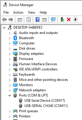
If there isn't 'USB Serial Device' or you see a 'Device Descriptor Failed' message on a connected USB Serial Device in Device Manager, try using:
- A different printer-style (USB-A Male to USB-B Male) USB cable
- A different USB port on the same computer
- A different computer
If none of these changes connect with the appropriate devices shown above, please contact Langmuir Systems Support.
Electrical
1: CrossFire is not responding to input
ELECTRICAL HAZARD - EXERCISE CAUTION
A. This issue is commonly caused by a power inlet issue. First, unplug the machine from the power outlet. Do other devices and appliances work on that outlet? Does the CrossFire machine work on a different power outlet?
B. Does the CrossFire's power switch illuminate when ipped to the “On” position? If so, move on to C; if not, open the machine's Electronics Enclosure. Are there any loose or disconnected wires between the power switch and the Power Supply? If everything is wired correctly and securely but the issue persists, reach out to Langmuir Systems Support for a replacement Power Inlet Assembly.
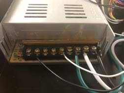
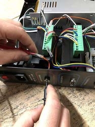
C1. If the power switch is illuminated but the issue persists, the next likely candidate is the Power Supply. When the machine is connected to power, does a green status LED illuminate on the Power Supply? If so, move on to D. If not: are there any loose or disconnected wires between the power switch and the Power Supply? Is the Power Supply wired correctly? If not, disconnect the machine from power and connect all loose wires as shown in this photo.
C2. It's possible that the voltage toggle switch it set to the incorrect orientation. Ensure that the toggle switch on the side of the power supply is set to match the voltage of the outlet the machine is connected to. Note: the toggle switch should not match the voltage of your plasma cutter.
C3. It's possible that the Power Supply is not outputting the correct output voltage. To check this, use a Digital Multimeter to probe any pair of the smaller black and white wire; the nominal DC voltage is 36V. If you are reading any other voltage, you'd need to adjust the Power Supply's output voltage: Disconnect the machine from power, then locate the potentiometer on the Power Supply (between the terminals and the green LED). Turning this pot will adjust the voltage; a few degrees in either direction is enough to adjust by several volts, so adjust carefully. To increase the voltage, turn the pot clockwise. Adjust the voltage until it is as close to 36V as possible.
If the issue persists, reach out to Langmuir Systems Support for a replacement Power Supply
D. If both the Power Switch and Power Supply have illuminated status LEDs, but the machine is still not responding to commands, the next likely candidate is the Step Drivers. When the machine is powered on, are there illuminated status LEDs on the Step Drivers? The Step Drivers are the series of black and green components around the motion control board on the right-hand side of the control box. If not, reach out to Langmuir Systems Support for further troubleshooting. Otherwise, the issue may stem from FireControl; refer to the Software section.
Plasma Cutter
1: Torch Not Firing (no air coming from nozzle)
It is important to note that a machine torch must be used in order for the CPC port on your Hypertherm plasma cutter to be functional. If a hand torch is used, the CPC port is locked out. This is a design choice on Hypertherm's end. You will either need to use a machine torch, or internally wire both the THC feature and the torch firing feature using the instructions linked below
Torch Firing Internal Wiring:
https://www.langmuirsystems.com/crossre/assembly#plasmawiring-section
THC Internal Wiring (RAW Voltage):
If the torch is not firing but air is coming from the nozzle, refer to the Misfire section.
A. The torch firing cable that connects your plasma cutter to the CNC electronics enclosure might be faulty. Will the torch fire if you short the torch firing cable? To test this, you will need the plasma cutter powered on and set in a safe position to fire the torch, and the torch firing cable unplugged from the "torch on/off" port of the control box. Once your plasma cutter is powered on and in a safe firing position, use a paperclip (or other thin piece of conductive metal) to bridge the torch firing cable's inner pin to the outer barrel. Doing so should force the torch to fire.
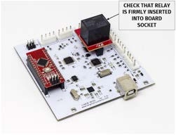
B. The torch firing relay might be faulty or loose. Ensure that the relay is firmly seated into its socket of the motion control board. The relay makes an audible "click" noise when switched from the open position (torch not firing) to the closed position (torch firing) and vice versa. If you power off your plasma cutter and initiate a manual torch fire in FireControl, can you hear the relay “click"?
C. Check that the relay is properly passing the signal along to the port. With your multi-meter in continuity mode, place one probe on the outside of the female barrel connector and one probe on the pin inside the barrel connector at the Torch On/Off Port. In FireControl, click Manual Torch Fire. You should have continuity between these two pins when a Manual Torch Fire is initiated. Be sure to click Manual Torch Fire again before plugging your torch back in to disarm it.

D. Next, check for continuity through the torch inlet female barrel connector on the electronics enclosure. Unplug the orange and purple blade connectors from the main wiring harness. With your multi-meter in continuity mode, place one probe on the orange blade connector and touch the other probe to either the outside barrel or the inside pin. You should have continuity to one of these. Next, probe the purple blade connector and probe the barrel connector again (if the orange had continuity to the inside pin, then probe the outside of the barrel connector and vice versa). If you are not getting continuity through both of these blade connectors to the port, you will need to have your inlet port replaced.
2: Torch Misfire (air coming from nozzle)
the X45 torch might not fire a pilot arc if the retaining cap is overtightened. An overtightened retaining cap may restrict oscillation of the electrode, preventing the torch from firing. The retaining cap should be snug enough to hold all of the consumables in place, but not as tight as possible; try slightly loosening the retaining cap.
If that doesn't do the trick, reach out to Razorweld directly for plasma cutter troubleshooting assistance. If a replacement or repair is necessary, the manufacturer's warranty on the plasma cutter is fullled through Jasic directly; all Razorweld 45 plasma cutters include a 3-year manufacturer's warranty.
Misres indicate an issue with either your CAM settings or an issue with the plasma cutter; they are not an issue with the CrossFire machine itself.
3: Non-standard Wiring Configurations
CPC Wiring
This image shows exactly how to use the CPC cable to connect to the torch firing and THC features of the CrossFire.
CPC Wiring
This image shows exactly how to use the CPC cable to connect to the torch firing and THC features of the CrossFire.
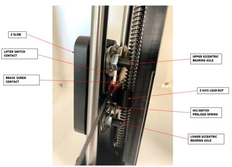
Z-axis
1: IHS Fail error message
A. The first thing you need to verify is that the Z-axis motor is functional. Manually jog the Z-axis motor by either clicking on the "+Z / -Z" buttons in FireControl or by pressing the "Page UP / Page DOWN" keys on your keyboard. Ensure that the Zaxis motor actually jogs, and that it jog the correct direction. If your Z-axis motor does not jog at all, proceed to section B below. If your Z-axis motor jogs the incorrect direction, then the polarity of the Z-axis step driver needs to be reversed. Refer to the Electronics section. If your Z-axis motor jogs the correct direction, proceed to C below.
B. If the Z-axis motor does not jog, you need to verify whether the motor itself is the faulty component. First, disconnect your CrossFire from power and check the Z-axis Motor Cable and Motor Port for signs of arc damage (burn marks, melting, etc). If no damage is present, try plugging the Z-axis motor into the X-axis motor port of the CNC electronics enclosure, then jogging it using X-axis commands. If the Z-axis motor is able to jog using X-axis commands, then the Z-axis step driver wiring should be inspected, or the Z-axis step driver should be replaced. If the Zaxis motor is not able to jog using X-axis commands, then the Z-axis motor should be replaced.
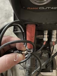
C. . It is possible that the brass switch components of the Z-axis assembly are separating from one another before the tip of the torch touches the metal sheet, as the IHS sequence intends. While watching the brass IHS contact switch components closely, manually jog the Z-axis motor by either clicking on the "+Z / -Z" buttons in FireControl or by pressing the "Page UP / Page DOWN" keys on your keyboard. If the brass switch components of the Z-axis assembly only separate from one another when the tip of the torch touches the metal sheet, proceed to step D; otherwise, continue with this step.
D. It is possible that the torch lead does not have enough slack coming from the cable support tube. If the torch lead—which runs between the top of the Cable Support Tube and the Torch Mount—is very taut, the IHS switch may be triggered before the torch contacts the workpiece. To resolve this. pull more of the Torch Lead up the Cable Support Tube, and try positioning the Torch Mount lower on the carriage so that the torch's neural position is closer to the workpiece.
E. It is possible that the Z-axis bearing preload might be too tight. Looking at the Z-axis assembly from the front of the machine; the bearing axles on the right hand side are adjustable. They are eccentric bolts, which can be turned with a 5mm wrench to adjust how much pressure is between the bearings and the rail. After backing the adjustable bearings off of the linear rails, but before tightening them again, rotate the bearings by hand to check for any that are "sticky" or “notchy" - if this is the case, lubricate the sidewall of the affected bearing with WD-40. You will need to use care when dialing in the preload; turn the eccentric bolt just enough to not have lash, and no more so that the Z slide moves up and down freely. While you are working on the bearing preload, also check the Z-axis linear rails for any bumps, protrusions, buildup of debris, or rust that would cause the Z-axis to not move up and down smoothly
F. It's possible that the IHS cable is not properly connecting the IHS contact switch system to the CNC electronics enclosure, or that the connection between the motion control board and the IHS port is faulty. All connections between the Z-axis IHS contact switch system and the motion control board are outlined in F1 through F5 below:
F1. Start by checking the set of two blade connectors that connect to the brass contact switches at the back of the Z-axis assembly. Ensure that the blades are properly mated between the Z-axis assembly and the IHS cable; disconnect the blades and reconnect them if necessary. Also, inspect that the other ends of the female blade cables are attached securely to the brass contacts.
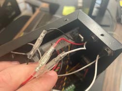
F2. Next, open the electronics enclosure and check the set of three blade connectors at the backside of the IHS port. Note that these wires are color-coded black, red, and white; and make sure that the colors match up appropriately. Ensure that the blades are properly mated between the IHS port and the main wiring harness, disconnect the blades and reconnect them if necessary.
F3. Next, trace the black and red color-coded wires from the IHS port to the motion control board (MCB). The black wire should correspond to the MCB position labeled '5v' and the red wire should correspond to the MCB position labeled 'IHS'. Gently tug the red and black wires individually to check for a loose connection to the MCB.
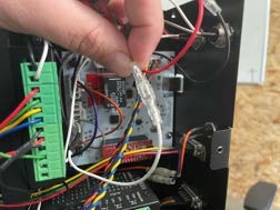
F4. Next, trace the white color-coded wire from the IHS port to the MCB. The white wire should correspond to the MCB position labeled 'GND'. Gently tug the white wire to check for a loose connection to the MCB.
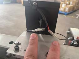
F5. IHS essentially functions by monitoring the continuity, and therefore the physical contact, between the brass contact switches located in the Z-axis assembly. The continuity is monitored via a 5v signal supplied to the black IHS wire (5v on the MCB), which leads to one of the brass contacts; and while the brass switches are in contact with one another, this 5v travels through the white IHS wire to the ground (GND on the MCB). If the motion control board does not read this 5v signal going into GND on the MCB, then it assumes the brass IHS contact switches are not in contact with one another.
F5a. While the table is connected vis USB and the brass contact switches are physically touching, set a digital multi-meter to measure DC voltage, place the red DMM lead at the black IHS wire associated with 5v and your black DMM lead at the white IHS wire associated with GND. You should read a steady voltage between 4.90v and 5v as shown in this image.
F5b. While the table is connected via USB and the brass contact switches are not physically touching: set a DMM to measure DC voltage, place the red DMM lead at the black IHS wire associated with 5v and your black DMM lead at the white IHS wire associated with GND. You should read 0v.
Automatic Torch Height Control (Thc)
1: THC Voltage Error
While the machine is in operation, there are two different THC error messages that may prompt: THC detecting a lack of voltage before the torch began moving (before the cut loop), or THC detecting a lack of voltage while cutting (during the cut loop). Determine which error message you're receiving and follow along with the associated subsection below:
Before Cut Loop
While not detecting voltage before the torch moved could be a THC issue, but is more likely indicative of a torch fire. To narrow this down, manually disable THC in FireControl by clicking the THC On/Off Toggle in the THC Control Panel, then run your G-code while THC is disabled. If your G-code cuts as expected while THC is disabled, proceed to the Grounding section below to troubleshoot this as a THC issue. If you still experience a cutting issue while THC is disabled, refer to the PLASMA CUTTER - Fire section of this guide to troubleshoot this as a torch fire.
After Cut Loop
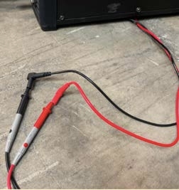
It is possible that low resistance between the motion control board and the frame of the machine is causing the voltage output from the VIM to not reach the LS-THC module. Using a Digital Multimeter (DMM), measure the Ohms of resistance between the USB shell and the frame of the machine. The goal is to have more than 10k Ohms (10,000 Ohms) of resistance here. If you measure less than 10k Ohms of resistance, proceed to the Grounding below; if you measure more than 10k Ohms of resistance, proceed to 4 below.
Grounding
Dismount the electronics enclosure from the leg tube of the machine and place it on a non-conductive surface, like a plastic bucket or a wooden stool. Keep all of the cables connected to the electronics enclosure. Measure the Ohms of resistance between the USB shell and the frame of the machine again. If you are reading 10K Ohms or more of resistance now, then your CNC electronics enclosure is not sufficiently isolated from the leg tube of the machine while mounted; ensure that you use the plastic isolator bracket and plastic washers when remounting the CNC electronics enclosure onto the leg tube, and that there is no metal-to-metal contact between the CNC electronics enclosure and the leg tube, including the screws that actually mount the CNC electronics enclosure. If you are still reading less than 10k Ohms of resistance, proceed.
While the electronics enclosure is still dismounted from the leg tube (and the laptop is still unplugged from its charging cable), disconnect all of the cables from the electronics enclosure: USB cable, power cable, motor cables, THC cable, IHS cable, and torch firing cable. Be sure to have the CNC electronics enclosure powered off while disconnecting and reconnecting the motor plugs. Since there is now no physical contact between the electronics enclosure and the frame, you should read infinite resistance (∞Ω) or open loop (OL) between the USB shell and the frame of the machine (infinite resistance and open loop are synonymous). Next, plug each cable back into the electronics enclosure one at a time, and take note of which connection causes the resistance to drop below 10k Ohms. Inspect the wiring associated with the connection in question for possible ground loops.
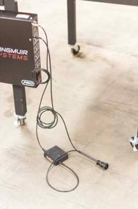
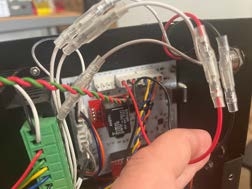
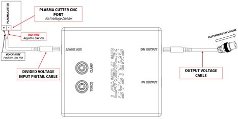
VIM
It is possible that the voltage output from the plasma cutter is not reaching the Voltage Input Module (VIM), or that the VIM is not outputting voltage to the CNC electronics enclosure. If your THC feature is wired to your plasma cutter via 50:1 divided voltage, proceed to the Divided Voltage section below; if your THC feature is wired to your plasma cutter via RAW voltage, proceed to the RAW Voltage section below.
Divided Voltage
Follow the steps below to verify that (A) the CNC port on your plasma cutter is working properly, (B) you have wired correctly into this port, and (C) that your VIM is wired correctly and generating the correct output voltage. Ensuring that your THC port is being fed a known-good voltage from your plasma cutter is essential to troubleshooting the THC system.
VIM wiring for Divided Voltage
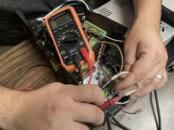
A. Verify that your plasma cutter's 50:1 voltage divider port is functioning properly while cutting. If your plasma cutter is equipped with a 50:1 voltage divider in the CNC port, you'll use your DMM to measure the DC Voltage across the two pins of this port while the plasma cutter is cutting.
Place the black electrode of the DMM on the negative pin (torch) of your voltage divider port, and the red electrode on the positive pin (work clamp). You may need to check your plasma cutter documentation to verify which pin is which on your CNC port. Next, using the STRAIGHT CUT feature in FireControl, perform a straight line cut with your machine with the THC panel toggled off in the control panel and measure the DC voltage across these two pins. Depending on your plasma cutter, the typical arc voltage while cutting will range between 60-150V; since the voltage divider is 50:1, you should see an output voltage of around +1.2 - 3V. If your voltage value is within range but is a negative reading, you have your two pins switched (positive and negative are reversed). If you are not getting the expected voltage here, contact your plasma cutter manufacturer to remedy the issue.
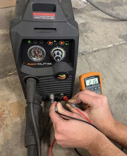
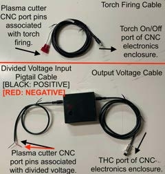
B. Next, you will need to use the provided Divided Voltage Input Pigtail Cable for wiring to the divided voltage port that you tested in step A.
Per the LS-THC user guide, the red wire should be connected to the negative pin, and the black wire should be connected to the positive pin. Once you've fashioned a suitable plug onto this pigtail end for connecting to your voltage divider port, use your DMM to verify that your wiring is correct. Touch the red electrode of the DMM to the inside of the barrel connector and the black electrode to the outside of the barrel connector. The DC voltage that you measure here should be identical to the value measured in step A. If you are getting a negative voltage here but the magnitude of this value is correct, you need to switch the polarity of your wiring on the plug to the 50:1 voltage
DO NOT TOUCH THE EXPOSED LEADS OF YOUR DMM WHILE PERFORMING THIS TEST
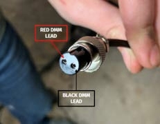
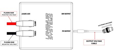
C. Verify that your VIM Box is wired and operating properly by plugging the barrel jack end of your Divided Voltage Input Pigtail Cable into the DIV INPUT socket on the VIM Box, then plug in the supplied Output Voltage Cable into the DIV OUTPUT socket on the VIM Box. Next, locate the free end of the Output Voltage Cable and note the pins labeled 1 and 2 on the front face of this connector. Using your DMM, touch the Red DMM lead to pin 1 and the black lead to pin 2.
Perform the same straight line cut as before with the THC Control panel toggled off in FireControl, and measure the DC voltage between these two pins as shown in the pictures below. Again, this voltage value should be positive. Your test setup should look exactly like the pictures below: you will notice that the DC voltage that is coming out of the VIM will be less than the input voltage that you measured in steps A and B.
This is because the VIM further divides the voltage for an effective total voltage division of 73:1. To figure out the ballpark voltage that you should be getting, multiply the voltage you found in steps A and B by 0.685 to get the value you should expect in this step.
For example: in step B we measured +2.16V, which multiplied by 0.685 gives us an expected voltage of +1.47V; this is very close to the +1.45V we measured in the photo. If you are getting good voltage values in steps A and B, but measure no voltage or an unexpected voltage coming out of the VIM box, double check the continuity of the two wires in the Output Voltage Cable. Verify that your Output Voltage Cable is plugged into the DIV OUTPUT socket on the VIM, and not the PV OUTPUT socket. If everything else checks out with the cable and you are getting a good input voltage in step A and B, you more than likely require a replacement VIM. Otherwise, proceed to the THC Module section.
RAW Voltage
Follow the steps below to verify that (A) your RAW Voltage Input Pigtails are connected to your plasma cutter correctly and that (B) your VIM Box is wired correctly and generating the correct output voltage. Ensuring that your THC port is being fed a known-good voltage from your plasma cutter is essential to troubleshooting the THC system.
VIM wiring for RAW Voltage
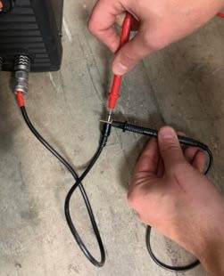
A. In this step, we need to verify that you have successfully connected to RAW voltage inside your plasma cutter and that the polarity of this wiring is correct.
Using a DMM, connect your black DMM lead to the black RAW voltage banana connector and connect your red DMM lead to the red RAW voltage banana connector (as shown below).
DO NOT TOUCH THE EXPOSED LEADS OF
YOUR DMM WHILE PERFORMING THIS TEST
Next, using the STRAIGHT CUT feature in FireControl, perform a straight line cut with your machine with the THC panel toggled off in FireControl and measure the DC voltage across these two connectors. Depending on your plasma cutter, the typical arc voltage while cutting will range between 60-150V. If you are getting a negative voltage reading here, you need to switch the connection points inside your plasma cutter or FireControl will read 0V (FireControl can only read a positive voltage). If you are getting no voltage reading at all, you will need to contact your plasma cutter manufacturer or a qualied electrician for better guidance on how to hook up to RAW voltage inside your plasma cutter.
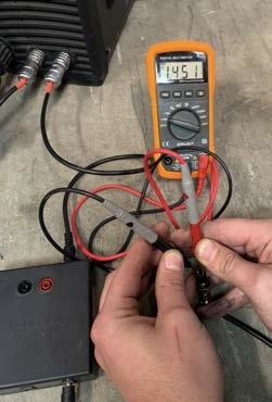
B. Plug the banana connector ends of the RAW Voltage Pigtail Cables into the corresponding color sockets on the top of the VIM. Next, plug in the supplied Output Voltage Cable into the PV OUTPUT socket on the VIM. Then, locate the free end of the Output Voltage Cable; note the pins labeled 1 and 2. Using the DMM, touch the red DMM lead to pin 1 and the black lead to pin 2. Perform the same straight line cut as before and measure the DC voltage between these two pins as shown in the pictures below.
DO NOT TOUCH THE EXPOSED LEADS OF
YOUR DMM WHILE PERFORMING THIS TEST
Again, this voltage value should be a positive voltage. You will notice that the DC voltage that is coming out of the VIM will be much less than what you measured in step A. This is because the VIM divides the RAW voltage input for an effective voltage division of 73:1. To figure out the ballpark voltage that you should be getting, divide the voltage you found in step A by 73. For example: in step A if you measured 110V, divide this by 73 and you should expect roughly 1.5V DC across the plug pins. If you are getting a good voltage value in step A, but measure no voltage or an unexpected voltage from the VIM box, double check the continuity in the Output Voltage Cable and that your Output Voltage Cable is plugged into the socket labelled PV OUTPUT. If everything looks good with the cable, you are more than likely experiencing a VIM module failure. If you are getting the expected positive voltage values in this step, but still showing no voltage in FireControl, proceed the THC Module section.
THC Module
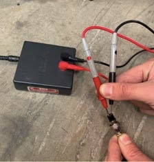
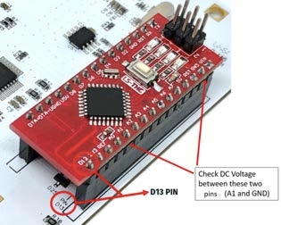
A. It is possible that the voltage from the Output Voltage Cable is not reaching the LS-THC module. Using a DMM, check DC voltage between the A1 pin and the GND pin on the THC module while FireControl is performing a straight cut. The reading between A1 and GND should match what you read from the Output Voltage Cable.
B. It is possible that the resting voltage on the LSTHC module is incorrect. While the USB cable is disconnected from the Motion Control Board, check DC voltage between the A1 pin and the GND pin on the THC unit using your DMM. You should be measuring close to 0V here. If you are getting a voltage reading that is greater than 100mV while the plasma cutter is off, your motion control board could be malfunctioning. If you are reading more than 0V, continue with this step; otherwise, move on to step C.
If you are reading more than 0v between A1 and GND while the plasma cutter is idle, unplug the IHS cable from the IHS port of the CNC electronics enclosure. If doing so causes the resting voltage to drop to 0v, then the IHS contact switch system is charging the frame of the machine with a low voltage that is being picked up by the LS-THC module. Use compressed air to blow any dirt/water from between the brass switch contact and the lead screw. Apply dielectric grease to the brass contact switches to prevent the issue from recurring.
C. Verify that reference voltage to the LS-THC module is correct. With the THC plugged into the white motion control board and the CNC electronics box plugged into your computer, you should see LEDs illuminate on both boards. Using a DMM, check DC voltage between the REF pin and the GND pin on the THC module. You should be measuring around 4.0v to 4.2v.
If the measurement is off, you'll want to determine if the issue is the LS-THC module itself, or whether the motion control board is not properly communicating the voltage signal to the LS-THC module. Unplug your USB cable from the CNC electronics enclosure and remove the LS-THC module from the motion control board socket by firmly pulling straight out. Find a suitable paperclip or small wire and stick one end down into the socket that would line up to the A1 pin on the LS-THC module if it were still plugged into the socket. Do the same for the GND socket. Make sure these wires are firmly seated down fully into the socket and are not touching each other. Plug back in your USB cable to the CNC electronics enclosure and measure the voltage between these two wires. If you do not read voltage between REF and GND on the LS-THC module, but you do read voltage between REF and GND on the motion control board, then your LS-THC module will need to be replaced. If you do not read voltage between REF and GND on the LS-THC module, and you also do not read voltage between REF and GND on the motion control board, then your motion control board will need to be replaced.
Limit Switch Kit
1: Homing in Incorrect Direction
This issue usually stems from the fact that FireControl starts keeping track of machine coordinates as soon as you first launch it, regardless of whether or not limit switches were configured. If the machine is manually jogged before it is homed it, the machine coordinate system becomes out of sync, possibly to such an extreme that FireControl thinks a coordinate of its current position is off the table, and thus incorrectly homes it back the incorrect direction.
Clicking "Reset Defaults" in the Machine Settings menu will reset the machine coordinates, and should make the CrossFire home in the correct direction. If you manually jog the machine before homing, click "Reset Defaults" again.
If the issue persists, reach out to Langmuir Systems support for additional assistance.
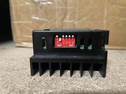
2: Limit Switch Activated when Homing
This issue is usually caused by an incorrectly-configured Step Driver. Each step driver has a series of 6 dip switches; inspect each one and ensure the dip switches are oriented as shown in the photo below:
If the issue persists, it's possible that you received an out-of-spec limit switch; reach out to Langmuir Systems support for a replacement.
3: Break-in Program throws Limit Switch Error
The break-in program was designed before the Limit Switch Kit came out. By design, the break-in program is supposed to run the entire area of the travel machine; thus, it may get very close to or cross a soft limit, prompting a soft limit error.
Take note of your soft limit values, then disable Limit Switches via the Machine Settings window and run the run-in program. Re-enable Limit Switches once the break-in program is complete.
Legacy (Mach 3) Crossfire Machines
1: Installation/Configuration
Mach3 needs to be installed and set up in a very specific way in order to work with the CrossFire machine. Please follow along with the instructions that are shown in the first video of our Mach3 tutorial series linked below:
https://www.langmuirsystems.com/software/mach3
The Mach3 installer and the necessary supplemental les can be found on our Legacy Downloads page:
2: Replacement Components
Gen1 CrossFire machines have been out of production since 2020; we have since run out of specific components for Legacy machines. If you are in need of components, reach out to Langmuir Systems support; some components are shared with the Gen2 CrossFire, while some require slight modification and additional components to work. For information on replacement Mach3 Motion Control Boards See the RNR Not Found error section.
3: RNR Not Found error
This error message indicates that either Mach3 was not sufficiently configured for use with the CrossFire, or the Motion Control Board has failed.
To ensure proper conguration, see the Installation/Conguration subsection.
We no longer carry Mach3 Motion Control Boards for the CrossFire. If your Motion Control Board has failed, you have a few options:
You can upgrade to a FireControl-compatible Electronics Enclosure by purchasing a CrossFire Z-Axis + THC Upgrade Kit, which also includes a mechanical Z-axis and all the necessary components for Automatic Torch Height Control. If you opt for this route, be sure to select "Gen 1 - Mach 3" under the "CrossFire Generation" dropdown menu,
Reach out to Langmuir Systems support to purchase a standalone FireControlcompatible Electronics Enclosure, separate from the Z-Axis + THC Upgrade Kit.
-
Purchase a generic Mach3 Motion Control Board from a third-party for use with your CrossFire. Langmuir Systems does not provide support or insight for such a modification.
Contact Langmuir Systems
My machine is experiencing an issue that isn't listed here, or I have a question that is not addressed in this guide.
Our support team is always happy to help!
Email: support@langmuirsystems.com
Phone: (833) 526-4797
Web: www.langmuirsystems.com/support
We also have a dedicated community of CrossFire users on our Forum! Another user may have had the same issue or question, with their solution publicly available to be referenced by others. Our support team is also active on the Forum.
Forum: forum.langmuirsystems.com