Creating and cutting out your projects is a 3-step process that starts with designing or utilizing previously designed projects. Next, you will program toolpaths (where the machine will cut) from these designs for use on the CrossFire CNC. Finally, you will use the programmed toolpaths to cut the parts out on the CrossFire.
The recommended software workflow for cutting parts on your CrossFire, CrossFire PRO, or CrossFire XR CNC Plasma is outlined below. This guide does not apply to Legacy Mach3-based machines but the general principles still apply.
Langmuir Systems has published guides for each step of this process that you can find by following the links below. Links to download the required programs are also listed below.
DESIGN Your Part (CAD)
The first step in creating parts for the CrossFire is designing or using previously designed projects. If you are just getting started, we recommend choosing a Ready-to-Cut project from FireShare to start.
There are numerous programs that enable you to design parts, signs, artwork, or anything else that can be made on a CrossFire CNC. We generally recommend selecting a program that is designed for the type of project you are working on.
Artwork or signs, for example, are easiest to design in a program created for that purpose like Adobe Illustrator or Inkscape. These programs give you the most flexibility and user-friendly interfaces without the hassle that comes with traditional CAD software. You must be able to design cuttable projects using any vector graphics software.
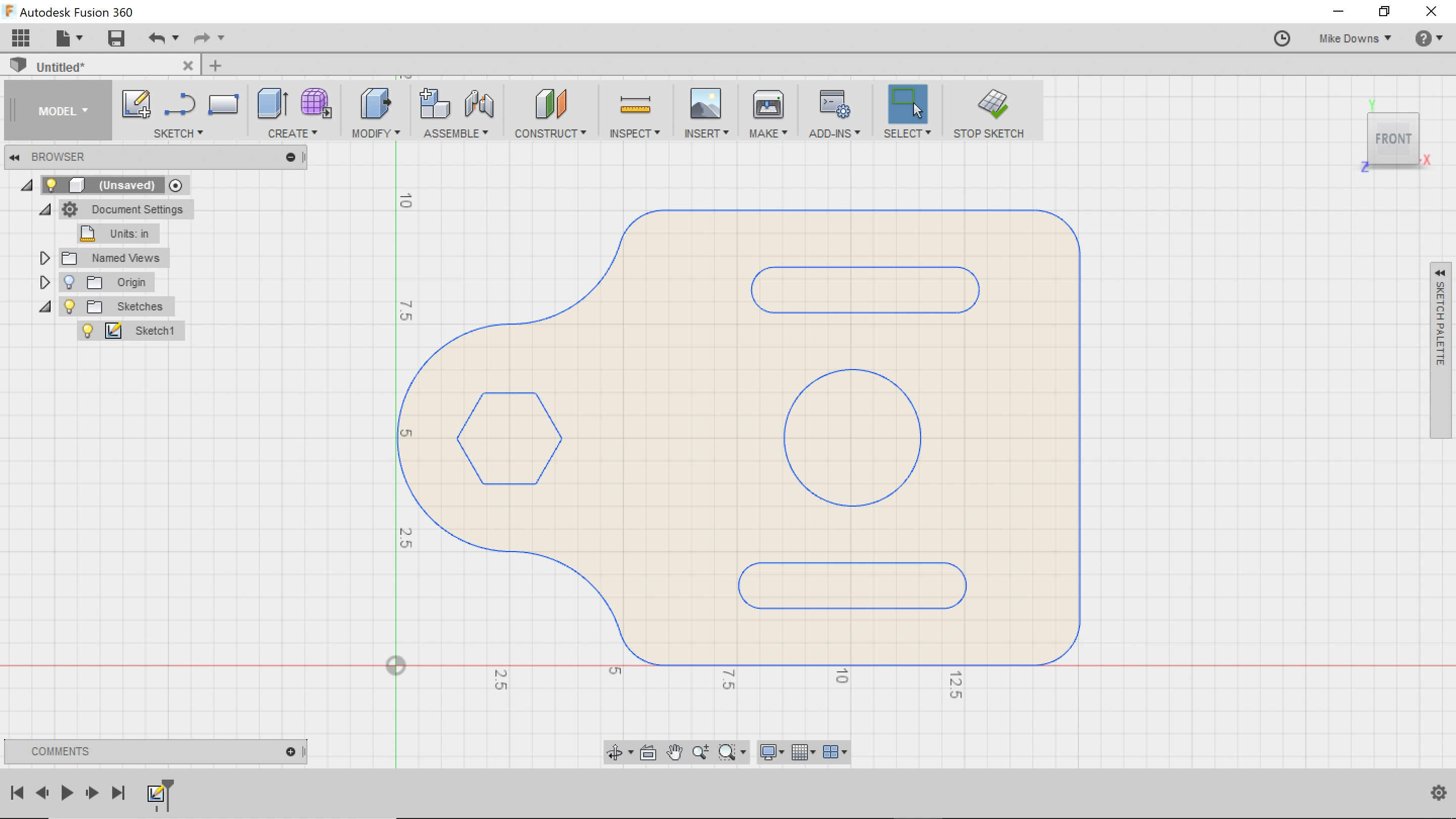
If you are designing parts for fabrication or other assembly, it's likely you need the power and precision of CAD software. For this purpose, Langmuir Systems recommends the use of Autodesk Fusion 360: a powerful design CAD and CAM software that is free to use for hobbyists and approved small businesses. Fusion 360 is both easy-to-use for CAD beginners and feature rich. We have published a comprehensive video guide covering installation, basic use, and designing real parts.
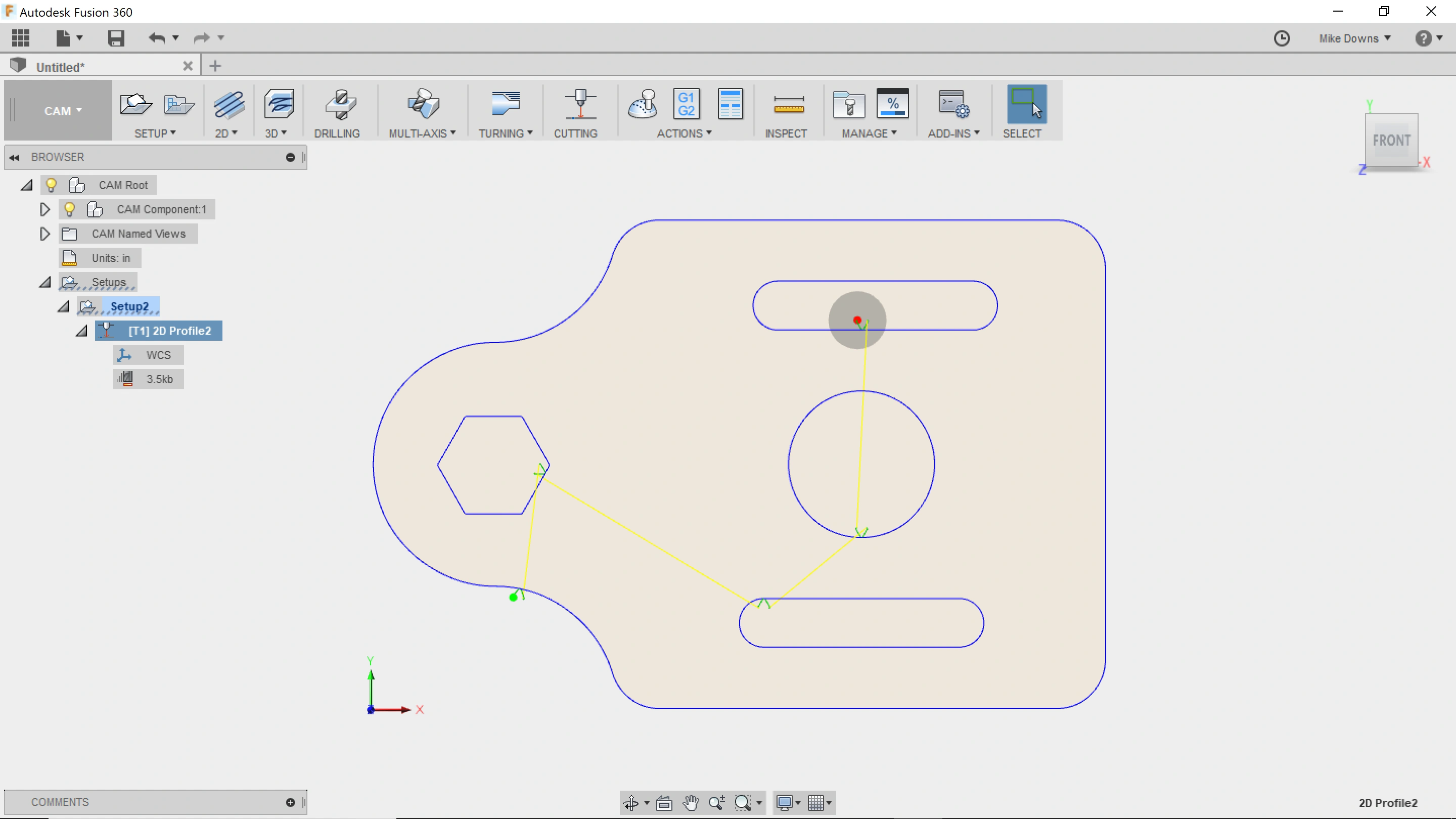
Once your design is complete, you will have a cuttable vector graphics image or a 2D CAD file (or a file within Fusion 360). The next step in the process is to create toolpaths: a series of coordinates and motion commands that the torch needs to move in order to cut your design. Generating this machine code or G-Code is largely an automated process but there are some complications as these toolpaths not only follow the lines of your project but also include additional geometry like lead ins or lead outs for piercing through your material.
If you are using Fusion 360 to design your project you will most likely want to use Fusion's CAM capabilities. In the Manufacturing space, you will specify your setup and cutting parameters such as cut speed, pierce delay, and lead-in geometry and Fusion will export these toolpaths as a G-code file that can be read by your machine's controller software (FireControl or Mach3).
If you were not using Fusion to design your project, you can still use it to perform the CAM for your file, but there are other options that may be simpler or more efficient and tailored for your workflow. Langmuir Systems recommends SheetCAM as a great alternative to quickly generate toolpaths for most design files. Learn more and purchase SheetCAM from Langmuir Systems.
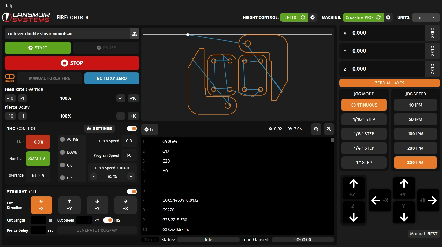
The final step in the process is to cut out your part on your CrossFire machine using our Motion Control Software, FireControl. You will first connect to the machine, then load a G-code file created by the CAM software. In FireControl, you can manipulate this program to fit it onto your material via scaling, rotating, or patterning. Then, with the material on the machine, press start to execute the program and cut out your part.